


Resistance Temperature Detectors
Understanding an application's performance requirements, such as operating temperatures, accuracy and repeatability demands, material compatibility issues, and environmental conditions, are crucial to designing the best RTD temperature sensor solution. In addition, many applications require special quality validation, testing, and certifications.
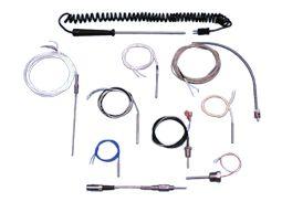
Durex Industries is prepared to provide the best RTD temperature sensor for your application requirements. Accurate, repeatable and robust RTD sensor (resistance thermometers) assemblies manufactured by Durex Industries provide fast temperature response and can be applied in most temperature measurement and control applications.
Product Technology Solutions
What are Resistance Temperature Detectors?
RTD sensors are thin film or wire wound resistor elements that use the Ohm resistance value to indicate a temperature value. The resistance simultaneously increases with temperature increase and vice versa.
Each Industrial RTD has a “calibration,” which indicates a specific base resistance value at a specific temperature (such as 100 Ohms at 0C) and a specific resistance vs temperature curve (DIN curve, JIS curve, etc).
Advantages of RTD Sensors Over Other Temperature Sensors
- Linear output
- Interchangeability
- Long term stability
Applications for Resistance Temperature Detectors
Industrial RTD temperature sensors are used in any application that requires temperature accuracy, the stability of readings over time, and repeatability of reading accuracy over time. They’re also used where application temperature ranges are -200C to 650C, as well as where high sensitivity to temperature change is not required.
RTD sensors are used for virtually every industry, but you typically find them in:
- Aerospace
- Analytical Equipment
- Food Service Equipment
- Semiconductor Equipment
- Food & Beverage Processing
Contact Durex Industries Today for RTD Temperature Sensors
All of our RTD sensors are quality tested and validated to meet your requirements. As a leading RTD temperature sensor manufacturer, our experienced team will work with you to develop the best, most economical custom RTD sensor solution for you.
To find out if resistance temperature detectors are right for your applications, view our temperature sensor element selection guide, or contact us today.
Resistance Temperature Detectors Specs & Options
Back to TopResistance Temperature Detector Specifications
Unless otherwise specified, Durex's RTD assemblies include photo-lithographically structured, high-purity platinum thin-film elements laser trimmed to precise resistance values. These sensors feature brief response times, excellent long term stability, low self heating and excellent resistance to vibration and temperature shocks.
Thermal Response Time
The response time T0.63 is the time the sensors need to respond to 63% of the change in temperature. The response time depends on the sheath dimensions, but can be as low as 1.2 seconds.
Long Term Stability
The change of ohmage after 1,000 hours at maximum operating temperature amounts to less than 0.03%.
Self Heating
To measure the resistance, an electric current has to flow through the element, which will generate heat energy resulting in errors of measurement. To minimize error, the testing current should be kept low (approximately 1mA for Pt-100).
Temperature error ΔT = RI²/E with:
E = self-heating coefficient in mW/K
R = resistance in kΩ
I = measuring current in mA
The self-heating coefficient (E) for the standard elements used in Durex RTD assemblies is 4 mW/K in air and 40 mW/K in water.
Measuring Current
Measurement current causes heating of the platinum thin-film sensor. The resulting temperature error is given by:
ΔT = P/E with the power loss P = I2R, and the self-heating coefficient E in mW/K.
The amount of thermal transfer from the sensor in the application determines how much measuring current can be applied. There is no bottom limit of the measurement current with platinum thin-film. The measurement current depends highly on the application in use.
We recommend at:
100Ω: typically 1mA, maximum 5mA
500Ω: typically 0.5mA, maximum 3mA
1000Ω: typically 0.3mA, maximum 2mA
2000Ω: typically 0.2mA, maximum 1mA
Nominal Values
The nominal or rated value of the sensor is the target value of the sensor resistance at 0°C. The temperature coefficient α is defined as
α = R100 - R0
100 - R0
(K-1) and has the numerical value of 0.00385 K-1 according to DIN IEC 751.
In practice, a value multiplied by 106 is often entered: TCR = 106 x R100 - R0
100 - R0 x (ppm/K)
In this case, the numerical value is 3850 ppm/K.
Temperature Characteristic Curve
The temperature characteristic curve determines the dependence of the electrical resistivity on the temperature. The following definition of the temperature curve according to DIN EN 60751 standard applies:
Tolerance Classes
| Class | ± limit deviations in °C (K) | IST AG designation | Temperature range |
| DIN 60751, class B | 0.30 + 0.005 x |T| | B | -200°C to 850°C |
| DIN 60751, class A | 0.15 + 0.002 x |T| | A | -90°C to 300°C |
| ⅓ DIN 60751, class B | 0.10 + 0.0017 x |T| | Y | -50°C to 150°C |
|T| is the numerical value of the temperature °C without taking into account either negative or positive signs.
Special selection of sensors upon request (pairings, groupings, special tolerances).
Calibration Services
Durex RTD calibrations are fully traceable to the National Institute of Standards and Technology (NIST) and are useful for defining the exact temperature coefficient of the sensor. For sensor applications below 32°F (0°C), a cryogenic range calibration is recommended. Certificates are supplied with all calibrations. Printed tables of interpolated values are only supplied with cryogenic range calibrations.
Style: R1L, R2L, R3L, R4L - The maximum rated temperature for these four styles is 500°F. Typically they are constructed with Teflon leads and the lead end is protected with an epoxy seal. This epoxy seal provides a moisture resistant barrier.
Style: R1M, R2M, R3M, R4M - The maximum rated temperature for these next four styles is 900°F. They are constructed with high temperature fiberglass insulated conductors. The lead end is sealed and protected with a high temperature cement.
Style: R1P, R2P, R3P, R4P - The maximum rated temperature for these last four styles is 1200°F. Their construction features highly compacted magnesium oxide insulation. Nickel conductors provide for extended temperature ratings and harsh environments.
Available Resistance Temperature Detector Elements
| Code | Element Type | Temperature Coefficient | Tolerance at 0°C |
| A | 100 ohm Platinum | .00385 | .1% |
| B | 100 ohm Platinum | .00385 | .06% |
| C | 100 ohm Platinum | .00385 | .03% |
| D | 500 ohm Platinum | .00385 | .1% |
| E | 1000 ohm Platinum | .00385 | .1% |
| F | 2000 ohm Platinum | .00385 | .1% |
| G | 100 ohm Platinum | .00392 | .1% |
| H | 100 ohm Platinum | .00392 | .03% |
| J | 120 ohm Nickel | .00392 | .5% |
| K | 604 ohm Nickel Iron | .00392 | .5% |
Resistance Temperature Detectors Case Studies
Back to TopTemperature Sensors for Food Service Oil Processing Equipment
RTD Temperature Probes For Analytical Instrumentation
Exhaust Gas Temperature Sensors
Aerospace Temperature Sensors
Pressure Washer Temperature Sensors
Thermocouples For Extruders
RTD Sensors For Food Service Frying Equipment
Custom Temperature Sensor Development Capabilities
Resistance Temperature Detectors Downloads
Back to TopResistance Temperature Detectors Catalog - 0115-2MB
Temperature Sensors Catalog - 0115-4MB
Techincal Data - RTD General Specifications 0115-250KB
Temperature Sensor Element Selection Guide - 200KB